A self-driving car needs to be aware of the actual objects around it in order to successfully navigate a road. Because of the rotating LiDAR sensor installed on the roof, which contributes to the creation of a three-dimensional image of the road surrounding the car.
LiDAR is not a novel concept; in fact, its inception coincided with the advancement of laser technology. In 1963, early LiDAR research was documented. Only government and military organizations were able to use LiDAR due to the high expense of the necessary laser equipment.
But thanks to recent price reductions, LiDAR is now affordable for do-it-yourselfers like us, so we can use it in our projects. The TFMini-S is one of the popular low-cost, precise LiDAR sensors.
First, a quick overview of LiDAR is provided. This tutorial will demonstrate how to connect the TFMini-S module with an Arduino to produce high-accuracy distance measurements.
How does LiDAR work and what does it mean?
LiDAR is an acronym for “Light Detection and Ranging” or, if you would rather, a combination of the terms “Light” and “RADAR.” With the exception of using light rather than radio waves, LiDAR and RADAR are similar.
Fundamentally, LiDAR operates by aiming a laser beam at a target. After bouncing off the item, the laser returns to the sensor. It is possible to estimate the distance to the item by timing how long it takes for that light to return to the sensor. The environment and the object’s reflection can affect the calculated distance.
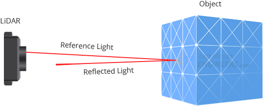
It is possible to quickly create a 3D map of the environment by sweeping or spinning a LiDAR sensor. To help with comprehension of what the LiDAR is detecting, this is typically displayed as a “point cloud.”

Overview of TFMini-S Hardware
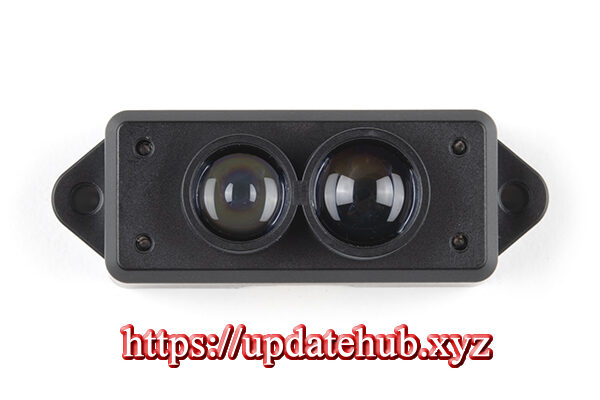
Benewake (Beijing) Co. Ltd. manufactures the high-accuracy, single-point ToF (Time of Flight) LiDAR sensor known as the TFMini-S. It is ideal for any robotics or interactive project that requires high-accuracy laser-based range.

With the TFMini-S, which is as small as a USB stick, you can now incorporate LiDAR into projects that were previously limited to smaller sensors like the SHARP GP-series infrared rangefinders.
As near as 10 centimeters and as far out as 12 meters, the TFMini-S can measure the distance between two objects.
Apart from its affordability, compact size, and extended range, the TFMini-S boasts a superior accuracy of ±6cm up to 6m and ±1% beyond that.
Range of Effective Detection
The effective detection range is dependent on the target object’s reflectivity, the weather, and lighting, just like it is with all LiDAR sensors.
The TFMini-S’s functioning range under different circumstances is displayed in the graph below.

0-10cm is TFMini-S’s blind zone; within this range, data is unreliable.
The TFMini-S’s operational range is 0.1-3 meters in harsh situations. Extreme conditions include outdoor glare, where the summertime midday illumination intensity is approximately 100 klux, and the identification of a black target, which has a 10% reflectivity.
The TFMini-S operates within a lighting intensity range of around 70klux under regular sunshine circumstances.
The TFMini-S can operate in low light conditions (0.1–12 m) or interior environments.
Interfaces for Communication
By default, the TFMini-S connects via the UART interface, using the RX and TX pins that are frequently used to communicate at 115200bps. By delivering the necessary commands, you may also set up the sensor to communicate via I2C.
The Frequency of Detection
The datasheet states that the TFMini-S has a maximum measurement rate of 1000 measurements per second (the default is 100). The right orders can be sent to alter this frequency. It should be mentioned that accuracy decreases with increased output frequency. Therefore, you should modify the output frequency based on the desired level of accuracy in the measurements.
Power Input
The datasheet states that the TFMini-S uses 5V and consumes roughly 140 mA when taking pictures. It has a maximum current consumption of about 200 mA.
However, the sensor was drawing roughly 70mA on its own throughout testing. Thus, you should anticipate using about 100mA if you utilize a 5V Arduino, a logic level converter, and the sensor. Consequently, the sensor can be powered by the USB connection (5V/500mA) without any problems for simple experiments.
Please remember that the power supply voltage fluctuations should not exceed 0.1V since the TFMini-S lacks overvoltage safety.
Levels of Logic
The I/O pins of the TFMini-S only have 3.3V logic, however it may be powered at 5V. Therefore, when utilizing the sensor with a 5V microcontroller, it is advised to apply a logic level converter. But, since 3.3V devices produce logic levels that are compatible with 5V devices, you can utilize a logic level converter if all you want to do is read the TFMini-S (in UART mode).
Technical Details
These are the details:
| Detection range | 10cm – 12m |
| Resolution | 1cm |
| Ranging Accuracy | ±6cm up to 6m and ±1% thereafter |
| Input Voltage | 5V |
| UART TTL Voltage | 3.3V |
| Current Consumption | 140mA (typ.), 800mA (peak) |
| Detection Frequency | 1 to 1000 scans per second (adjustable) |
| Light Wavelength | 850nm |
| Field of view | 2.3° |
| Communication interfaces | UART and I2C |
| Baud Rate | 115200 |
Please see the datasheet provided below for additional details regarding the TFMini-S LiDAR sensor.
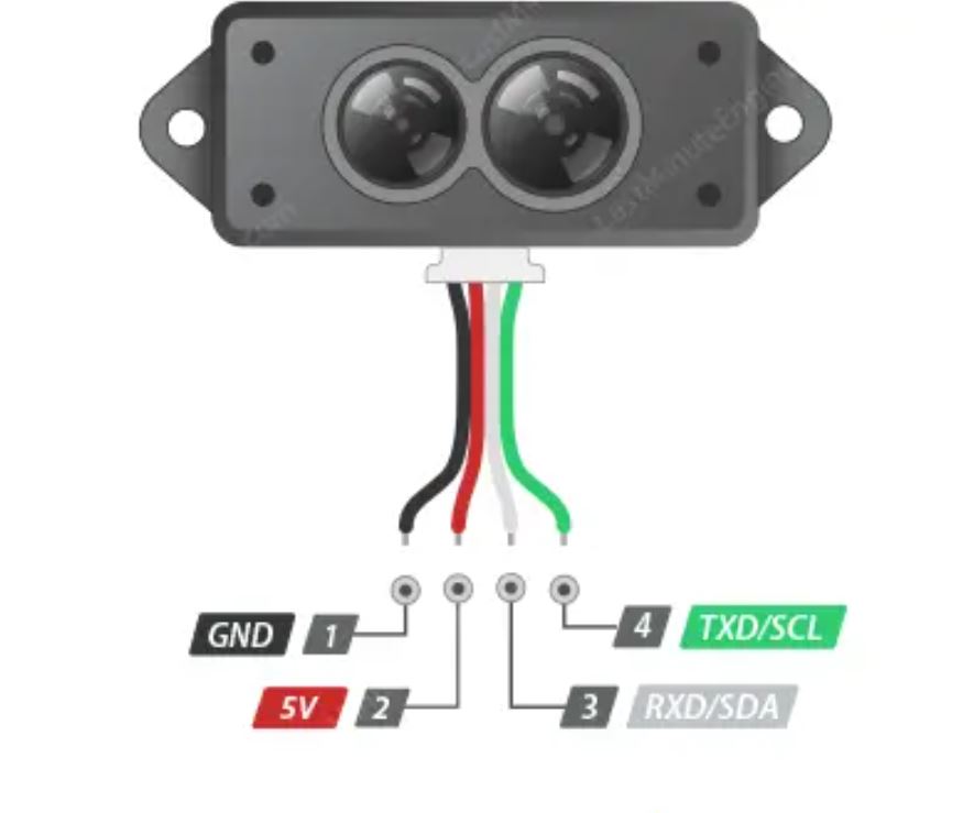
Pinout for TFMini-S
Let’s now examine the pinout. It has four pins on the TFMini-S.


Linking an Arduino Board with a TFMini-S Sensor
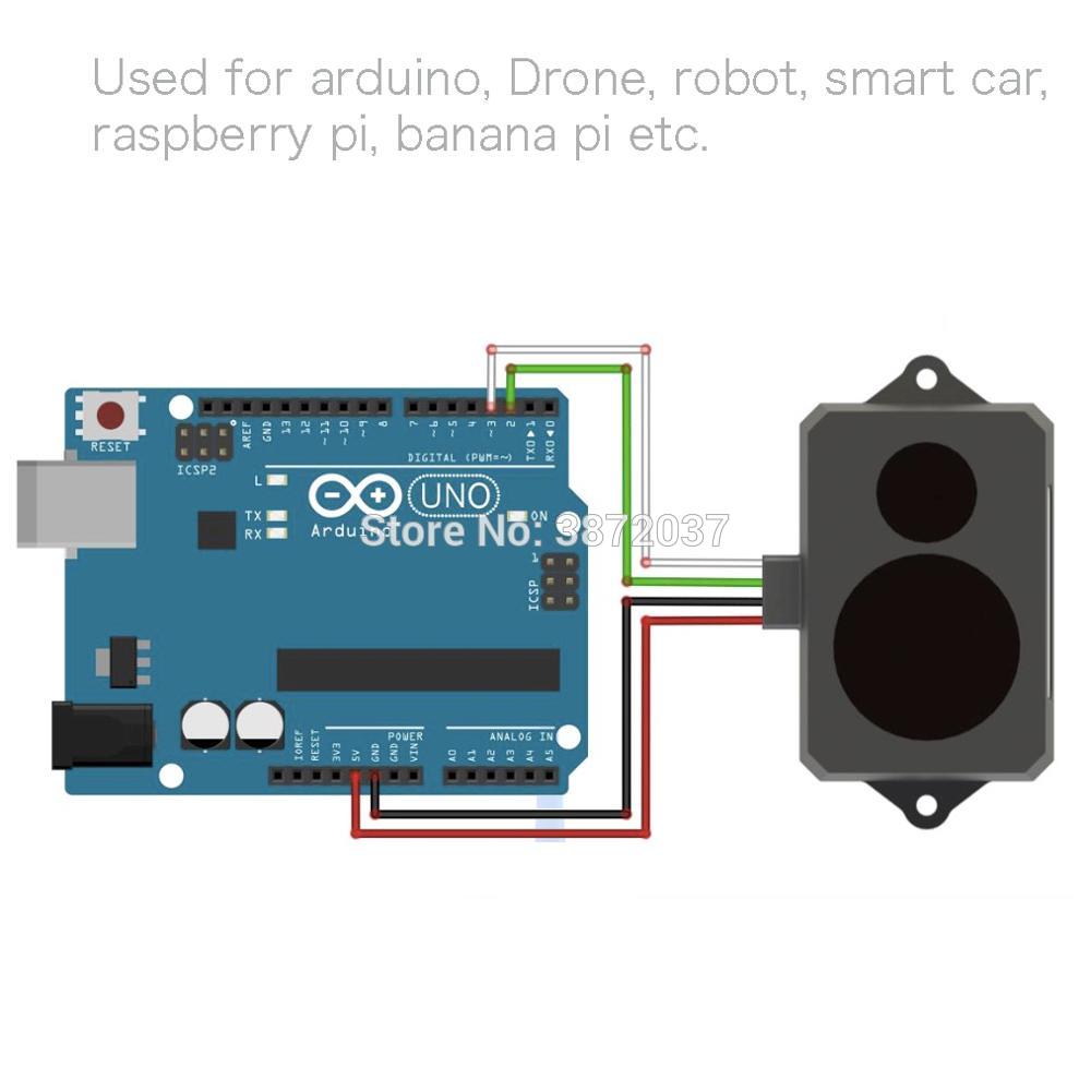
It’s really easy to connect an Arduino to a TFMini-S sensor. Only four wires need to be connected.
Start by attaching the TFMini-S sensor’s Red wire (VCC) to the 5V output pin of the Arduino and its Black wire (GND) to the GND pin.
As we will be building a software UART, now connect the White wire (RXD/SDA) of the TFMini-S sensor to the digital pin 3 of the Arduino and the Green wire (TXD/SCL) to the digital pin 2 of the Arduino.
The circuit construction is depicted in the image below.
Example Code for Arduino
After connecting everything, let’s run a quick sketch to show off the TFMini-S sensor’s features.
#include <SoftwareSerial.h>   //header file of software serial port
SoftwareSerial Serial1(2, 3); //define software serial port name as Serial1 and define pin2 as RX & pin3 as TX

int dist;                     //actual distance measurements of LiDAR
int strength;                 //signal strength of LiDAR
int check;                    //save check value
int i;
int uart[9];                   //save data measured by LiDAR
const int HEADER = 0x59;      //frame header of data package


void setup()
{
  Serial.begin(9600);         //set bit rate of serial port connecting Arduino with computer
  Serial1.begin(115200);      //set bit rate of serial port connecting LiDAR with Arduino
}


void loop() {
  if (Serial1.available())                //check if serial port has data input
  {
    if (Serial1.read() == HEADER)        //assess data package frame header 0x59
    {
      uart[0] = HEADER;
      if (Serial1.read() == HEADER)      //assess data package frame header 0x59
      {
        uart[1] = HEADER;
        for (i = 2; i < 9; i++)         //save data in array
        {
          uart[i] = Serial1.read();
        }
        check = uart[0] + uart[1] + uart[2] + uart[3] + uart[4] + uart[5] + uart[6] + uart[7];
        if (uart[8] == (check & 0xff))        //verify the received data as per protocol
        {
          dist = uart[2] + uart[3] * 256;     //calculate distance value
          strength = uart[4] + uart[5] * 256; //calculate signal strength value
          Serial.print("distance = ");
          Serial.print(dist);                 //output measure distance value of LiDAR
          Serial.print('\t');
          Serial.print("strength = ");
          Serial.print(strength);             //output signal strength value
          Serial.print('\n');
        }
      }
    }
  }
}
Open your serial monitor when the sketch has been uploaded, and adjust the baud rate to 9600 bps.
Try aiming the sensor at nearby objects. The measured distance should start to stream by.
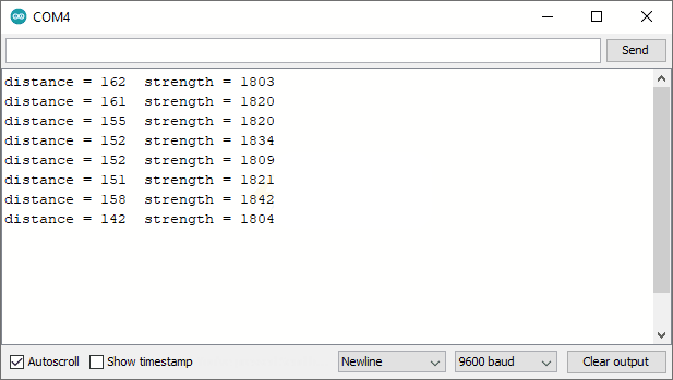
When the TFmini-S is turned on, a red light should be visible inside the transmitting lens when viewed from the front. If no information is presented, check to see if the device is connected correctly.
TFMini Program
A strong tool for evaluating TFMini sensors is the TFMini program. Although it is free, the program is limited to Windows use.
This software is available for download from the official Benewake website.

Utilizing TFMini Program
The program is packaged as a “Portable” RAR file. After downloading, extract it to the desired folder. Run the WINCC_TF.exe program. The startup of the software will look like this.

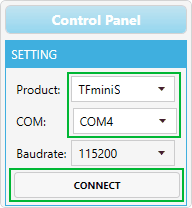
Locate the Settings area and select the product type TFMiniS. The COM port that the TFMini-S is connected to should then be chosen. In the end, click the Connect button.
The application starts showing a distance-over-time waveform in the “Time Line Chart” area as soon as the device is attached. The current distance (Dist), the number of effective data points per second (Effective Points), and the signal strength (Strength) are shown in the “Real Time Data” section below.

