When we were younger, the gyroscopes at the science fair never ceased to astound us because of their peculiar movements and apparent defiance of gravity. Their special qualities make them indispensable in anything from sophisticated space shuttle navigation systems to tiny remote-controlled aircraft.
Micromachined gyroscopes have been successfully constructed in recent years by clever engineers. A whole new range of cutting-edge applications, including as gesture recognition, improved gaming, augmented reality, panoramic photo capture, car navigation, and fitness tracking, have been made possible by these MEMS (microelectromechanical system) gyroscopes.
The accelerometer and gyroscope are unquestionably remarkable in their own right. But when we combine them, we may receive extremely accurate information on the orientation of an object. Here’s where
Here’s where the MPU6050 comes into play. We can measure rotation along all three axes, static acceleration due to gravity, and dynamic acceleration due to motion using the MPU6050 since it has both an accelerometer and a gyroscope built in.
Understanding the operation of accelerometers and gyroscopes is a good thing before we utilize the MPU6050 in our Arduino project.
How Do You Operate an Accelerometer?
Imagine a ball inside a three-dimensional cube to get an idea of how accelerometers operate.

Under the assumption that the cube is in space, where all objects are weightless, the ball will just float in the cube’s center.
Now imagine that every wall is a particular axis.
The ball will surely strike wall X if we abruptly move the box with acceleration 1g (one G-force is equal to gravitational acceleration of 9.8 m/s2). The force the ball applies to wall X may be measured, and the resultant value along the X axis is 1g.
Let’s observe what occurs when we set the cube down on our planet. As seen in the diagram below, the ball will just fall against wall Z, applying a force of one gram.
Even though the box isn’t moving in this instance, the Z axis value is still 1g. This is due to the ball being pulled downward by gravity, which is essentially a type of acceleration, with a force of one gram.
Although this model is not an exact replica of the construction of a real accelerometer sensor, it is frequently helpful in explaining why the output signal of an accelerometer is usually expressed in ±g, why an accelerometer at rest reads 1g in the z-axis, and what readings you can anticipate from an accelerometer at various orientations.
In the actual world,
Micro-Electro-Mechanical Systems (MEMS fabrication technique) are the foundation of accelerometers. Now let’s investigate the operation of a MEMS accelerometer.
What’s the Process of a MEMS Accelerometer?
An accelerometer, or micro-machined structure, is constructed on top of a silicon wafer and is known as a MEMS (Micro-Electro-Mechanical System).
Polysilicon springs are used to suspend this construction. When the structure accelerates along the X, Y, or Z axes, it permits deflection.
The capacitance between fixed plates and plates attached to the hanging structure varies as a function of deflection. The acceleration along that axis is proportionate to this change in capacitance.
This change in capacitance is processed by the sensor, which then outputs an analog voltage.
How Do Gyroscopes Operate?
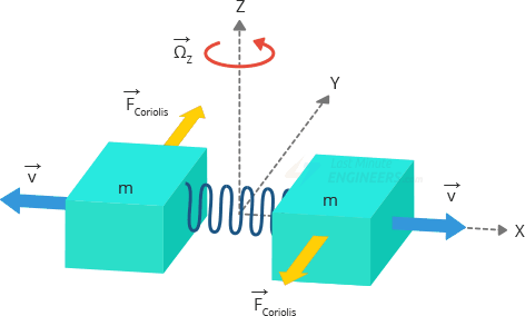
Gyroscopes measure angular rotation, whereas accelerometers measure linear acceleration. They measure the force produced by the Coriolis Effect in order to achieve this.
The Coriolis Effect
According to the Coriolis Effect, when a mass (m) moves with a velocity (v) in a particular direction and an external angular rate (Ω) is applied (Red arrow), the mass moves perpendicularly due to the force produced by the Coriolis Effect (Yellow arrow). The applied angular rate has a direct bearing on the displacement’s value.
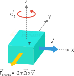
Imagine two masses oscillating at a constant frequency and in opposite directions. The Coriolis effect that each mass produces is directed in different directions when an angular rate is applied, which causes a corresponding change in capacitance between the masses. The angular rate can be computed by detecting this change in capacitance.
How Do MEMS Gyroscopes Operate?
To respond to the coriolis effect, the MEMS sensor is made up of a proof mass (which is made up of the four pieces M1, M2, M3, and M4) that is continuously oscillating. They go in the horizontal plane both inward and outward at the same time.

The Coriolis force acting on the moving proof mass causes the vibration to change from horizontal to vertical as we start to rotate the construction.
Depending on the axis the angular rotation is applied along, there are three modes.
Roll Mode: The coriolis effect causes M1 and M3 to move up and down out of the plane when an angular rate is applied along the X-axis. The term “Roll Mode” refers to the shift in roll angle that results from this.
Pitch Mode: M2 and M4 will move up and down out of the plane when an angular rate is applied along the Y-axis. Pitch Mode gets its name from the fact that this alters the pitch angle.
Yaw Mode: M2 and M4 move horizontally in different directions when an angular rate is applied along the Z-axis. Yaw Mode gets its name from the fact that this alters the yaw angle.

Overview of MPU6050 Module Hardware
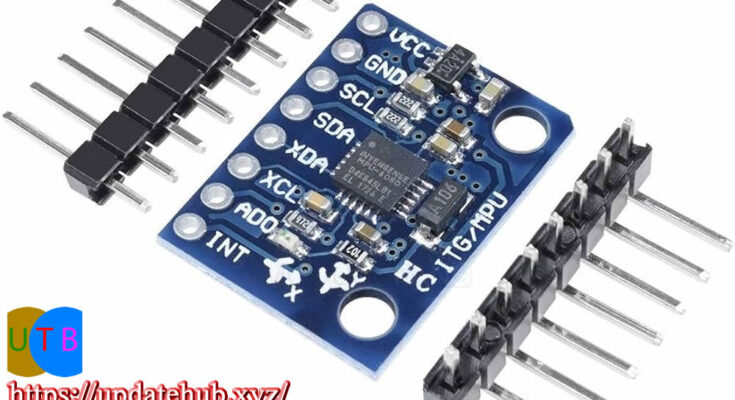
The MPU6050, a low-power, low-cost 6-axis MotionTracking chip, is the central component of the module. It combines a Digital Motion Processor (DMP), a 3-axis accelerometer, and a 3-axis gyroscope into a compact 4mm x 4mm box.
It is capable of measuring dynamic acceleration brought on by motion, shock, or vibration, as well as angular momentum or rotation along all three axes.

You can use the module safely with a 5V logic microcontroller such as Arduino because it comes with an on-board 3.3V regulator, the LD3985.
When in idle mode, the MPU6050 uses a mere 5μA and during measurements, it uses less than 3.6mA. Its low power consumption allows it to be utilized in battery-operated gadgets.
The module also features a Power LED, which turns on when the power is applied.
How to Measure Acceleration
An on-chip accelerometer measuring acceleration over four programmable full scale ranges of ±2g, ±4g, ±8g, and ±16g is featured in the MPU6050.
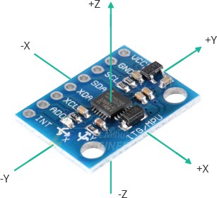
Three 16-bit analog-to-digital converters that sample the three axes of movement (along the X, Y, and Z axes) simultaneously are built into the MPU6050.
Calculating Rotation
An on-chip gyroscope on the MPU6050 is capable of measuring angular rotation over four configurable full scale ranges: ±250°/s, ±500°/s, ±1000°/s, and ±2000°/s.
Three additional 16-bit analog-to-digital converters that sample the three axes of rotation (along the X, Y, and Z axes) simultaneously are built into the MPU6050. It is possible to change the sampling rate from 3.9 to 8000 samples per second.
Temperature Measurement
An integrated temperature sensor in the MPU6050 can detect temperatures between -40 and 85°C with an accuracy of ±1°C. Keep in mind that the temperature being measured here is that of the silicon die, not the surrounding air. Rather than recording absolute temperatures, these measures are usually used to detect temperature fluctuations or to adjust for calibration errors in accelerometers and gyroscopes.
The Interface between I2C and
Through the I2C interface, the module may communicate with the Arduino.0x68HEX and 0x69HEX are the two distinct I2C addresses that it supports. This makes it possible to use two MPU6050s.
either to prevent address clashes with other devices on the bus or to stay on the same bus.

The module’s I2C address is determined by the ADO pin. A 4.7K resistor is used to pull this pin down. As a result, the I2C address is 0x68HEX by default when the ADO pin is disconnected; nevertheless, 0x69HEX is the I2C address that results from connecting the pin to 3.3V, which pulls the line HIGH.
Including External Sensors
By attaching external sensors to the MPU6050 module, you can increase its precision even more. The MPU6050 can be linked to these external sensors by a separate I2C bus (XDA and XCL), which is the second one.

A magnetometer, which measures magnetic fields along three axes, is typically attached to this external connection. With three degrees of freedom for the accelerometer and three for the gyroscope combined, the MPU6050 has six degrees of freedom. The degree of freedom of the sensor is increased from 6 to 9 DOF by adding a magnetometer.
Technical Details
These are the details:
| Operating Voltage | 5V (typical) |
| Accelerometer Range | ±2g, ±4g, ±8g, ±16g |
| Gyroscope Range | ±250°/s, ±500°/s, ±1000°/s, ±2000°/s |
| Temperature Range | -40 to +85°C |
| Absolute Maximum Acceleration | Up to 10,000g |
For more information, please refer to the datasheet below.
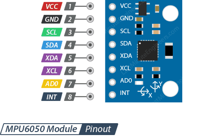
Pinout for MPU6050 Module
The pinout of the MPU6050 module is as follows:


Connecting an Arduino to an MPU6050 Module
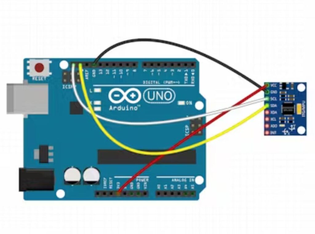
Now let’s connect the Arduino to the MPU6050 module.
Links are simple to make. Attach the GND pin to ground and the VCC pin to the Arduino’s 5V output first.
Currently, the pins utilized for I2C connection remain. Keep in mind that the I2C pins on each Arduino board vary and need to be linked properly. The SDA (data line) and SCL (clock line) on Arduino boards with the R3 layout are located on the pin headers near the AREF pin. They go by the names A5 (SCL) and A4 (SDA) as well.
Take a look at the table below for easy access.
| SCL | SDA | |
| Arduino Uno | A5 | A4 |
| Arduino Nano | A5 | A4 |
| Arduino Mega | 21 | 20 |
| Leonardo/Micro | 3 | 2 |
The diagram below shows how to connect everything.
Example Code for Arduino
This is a basic program that prints the temperature, angular rotation, and linear acceleration from the MPU6050 module on the serial monitor.
#include <Adafruit_MPU6050.h>
#include <Adafruit_Sensor.h>
#include <Wire.h>

Adafruit_MPU6050 mpu;

void setup(void) {
	Serial.begin(115200);

	// Try to initialize!
	if (!mpu.begin()) {
		Serial.println("Failed to find MPU6050 chip");
		while (1) {
		  delay(10);
		}
	}
	Serial.println("MPU6050 Found!");

	// set accelerometer range to +-8G
	mpu.setAccelerometerRange(MPU6050_RANGE_8_G);

	// set gyro range to +- 500 deg/s
	mpu.setGyroRange(MPU6050_RANGE_500_DEG);

	// set filter bandwidth to 21 Hz
	mpu.setFilterBandwidth(MPU6050_BAND_21_HZ);

	delay(100);
}

void loop() {
	/* Get new sensor events with the readings */
	sensors_event_t a, g, temp;
	mpu.getEvent(&a, &g, &temp);

	/* Print out the values */
	Serial.print("Acceleration X: ");
	Serial.print(a.acceleration.x);
	Serial.print(", Y: ");
	Serial.print(a.acceleration.y);
	Serial.print(", Z: ");
	Serial.print(a.acceleration.z);
	Serial.println(" m/s^2");

	Serial.print("Rotation X: ");
	Serial.print(g.gyro.x);
	Serial.print(", Y: ");
	Serial.print(g.gyro.y);
	Serial.print(", Z: ");
	Serial.print(g.gyro.z);
	Serial.println(" rad/s");

	Serial.print("Temperature: ");
	Serial.print(temp.temperature);
	Serial.println(" degC");

	Serial.println("");
	delay(500);
}