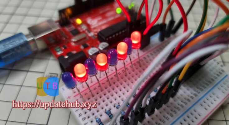
Anyone familiar with Arduino can operate LED lights. It’s not an issue to have one LED, three or five LEDs, but eight LEDs? The pins are almost completely used up after attaching the LED, yet there isn’t a problem with the program! Here’s where the 74HC595 is useful. With just three pins, it can operate over eight LEDs!
A shift register is 74HC595 (Shift Register). With this microcontroller, controlling eight outputs simultaneously requires just three Arduino pins. A pin called 74HC595 can be linked in series to increase output. 16 LED lights can be controlled if two are connected in series, and so on. We’ll practice using this time
just one 74HC595.
Furthermore, there are additional alternatives, such as STP16C596, in addition to the 74HC595 shift registers. 16 channels can be provided by a single chip, and each channel can supply up to 120mA of current—much more than the 25–35mA of 74HC595—but we The most popular 74HC595 will be introduced first in this example.
Friends who would like to learn about the shift register principle can view this explanation on WiKi:
74HC595 has 16 pins, and the name of each pin is as follows:

There are 16 pins of 74HC595, among which Q0~Q7 can be used to connect 8 LEDs. In this example, the connection method of other pins is as follows:
- VCC => 5V
- DS => PIN 11 (Data pin)
- OE => GND
- STCP => PIN 8 (Latch pin)
- SHCP => PIN 12 (Clock pin)
- MR => 5V
- GND => GND

It’s actually not that hard to connect, but there are a lot of wires and every LED need a 220 ohm resistor. After looking at the wiring diagram, I think a lot of people are puzzled, but make sure to connect all the wires correctly!
Data is delivered via the shiftOut() function, and the function requires byte data, which is an integer between 0 and 255 that represents 8-bit data. One bit, denoted by 0 and 1, is present in each channel. The LED’s ON/OFF states are indicated by the terms LOW and HIGH.
In the event that you desire the first, third, fifth, and seventh lights to be on and the second, fourth, sixth, and eighth lights to be incorrect, that would be 10101010, or 170 in decimal.
Those who have completed computer classes should be familiar with the conversion process, but many have forgotten it^^. It is irrelevant. There are lots of websites with converting features. You can look it up on Google. Jason found the following webpage. You are welcome to consult it.

The example we are going to do is very simple, that is, let 8 lights, 4 lights turn on alternately, first light 1, 3, 5, 7, then 2, 4, 6, 8, that is, 10101010, 01010101, converted to ten The carry is 170 and 85.
Arduino Code
int latchPin = 8;  // Latch pin (STCP腳位)
int clockPin = 12; // Clock pin (SHCP腳位)
int dataPin = 11;  // Data pin (DS腳位)

void setup()
{
  // Set all the pins of 74HC595 as OUTPUT
  pinMode(latchPin, OUTPUT);
  pinMode(dataPin, OUTPUT);
  pinMode(clockPin, OUTPUT);
}

void loop()
{
  digitalWrite(latchPin, LOW);  // 送資料前要先把 latchPin 設成低電位
  shiftOut(dataPin, clockPin, LSBFIRST, 170);  //送出資料,170就是2進位的10101010
  digitalWrite(latchPin, HIGH); // 送完資料後要把 latchPin 設成高電位
  delay(300);
  digitalWrite(latchPin, LOW);
  shiftOut(dataPin, clockPin, LSBFIRST, 85);  //85就是2進位的01010101
  digitalWrite(latchPin, HIGH);
  delay(300);
}
The shiftOut() method, which takes four parameters (dataPin, clockPin, data order (LSBFIRST from left to right, MSBFIRST from left to right), and data, is the most crucial function in the program. For the data sequence, we utilize LSBFIRST, and we put in 170 or 85.
Another crucial detail is that the latchPin needs to be set to low level before shiftOut() can transfer data, and it needs to be set back to high level once the data has been sent.
We utilized two programs, transmitting data at intervals of 0.3 seconds: 170 and 85, respectively. You can see the LED begin to flash and alter when the program has been written!

Another example is a common running water lamp. In this example, the 8th lamp starts to light up, then lights up to the 1st lamp in sequence, and then turns off all lights, and then repeats.
Complete Arduino Code
int latchPin = 8;  // Latch pin (STCP腳位)
int clockPin = 12; // Clock pin (SHCP腳位)
int dataPin = 11;  // Data pin (DS腳位)

byte leds = 0;    // 亮燈的LED數量
void setup()
{
  // Set all the pins of 74HC595 as OUTPUT
  pinMode(latchPin, OUTPUT);
  pinMode(dataPin, OUTPUT);
  pinMode(clockPin, OUTPUT);
}

void loop()
{
  leds = 0; // 一開始燈全滅,所以設為0
  updateShiftRegister();  //進行送資料的副程式
  delay(500);
  for (int i = 0; i < 8; i++) //依序亮燈
  {
    bitSet(leds, i);    //
    updateShiftRegister(); //進行送資料的副程式
    delay(100);
  }
}

void updateShiftRegister()
{
   digitalWrite(latchPin, LOW);
   shiftOut(dataPin, clockPin, LSBFIRST, leds);
   digitalWrite(latchPin, HIGH);
}


