This Arduino UNO with infrared sensor RPM tachometer is straightforward but efficient. It uses interrupts to count the revolutions of a rotating object and shows the RPM on an OLED screen. This versatile tool is a great asset to many projects and sectors because it may be used for machine control and monitoring.
How is the tachometer operated?
The sequence of actions this tachometer takes to show the motor speed is listed below.
1. Sensor setup: To begin, position an infrared sensor close to a rotating object that has gaps or a reflecting marking on it. The marker is detected by the IR sensor as it moves in front of it.
2. Handling interruptions: The Arduino board is configured to react to interrupts with a falling edge. A counter is increased at the occurrence of an interruption, thereby counting half a revolution.
3. RPM computation: The following formula is used to determine the RPM (Revolutions Per Minute):
RPM = (Counter / 2) * 60
In this case, dividing by two indicates the number of half-revolutions inside a one second interval; multiplying the result by 60 yields the RPM.
4. Display update: The OLED panel shows the computed RPM value. Readings of the RPM are shown in real time, with a secondly update.
5. Constant monitoring: By repeating this procedure, we are able to precisely determine the motors’ RPM.
Components required
- Arduino Nano or Arduino Uno
- IR Sensor
- 0.96 inch OLED Display
Introduction to IR sensor
An electronic gadget called an infrared sensor uses light emission to identify objects in its environment. In addition to measuring an object’s heat, an infrared sensor may detect motion.
In general, everything in the infrared spectrum radiates heat in some way. Although these radiations are invisible to the human eye, they can be detected by an infrared sensor.
An infrared LED (Light Emitting Diode) serves as the emitter, and an infrared photodiode serves as the detector. The photodiode and the IR LED have the same wavelength of infrared light that it can detect.
The resistances and output voltages of a photodiode are affected by the amount of infrared light it receives.
The IR sensor’s pinout is shown below.

- VCC: This is the power supply pin.
- OUT: This is a 5V TTL logic output pin. LOW implies that no motion is detected, and HIGH indicates that motion is detected.
- GND: This is a ground pin.
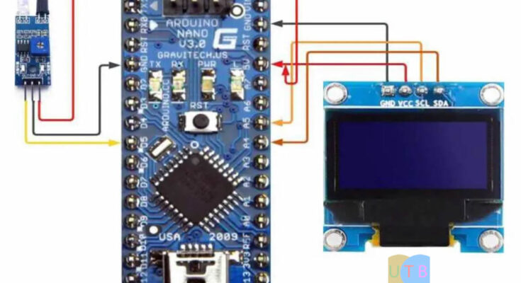
Circuit diagram

| OLED Pin | Arduino Nano Pin |
| VCC | 5V Pin |
| GND | GND of Arduino Nano |
| SDA | A4 |
| SCL | A5 |
| IR Pin | Arduino Nano Pin |
| VCC | 5V Pin |
| GND | GND of Arduino Nano |
| OUT | D5 |
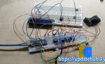
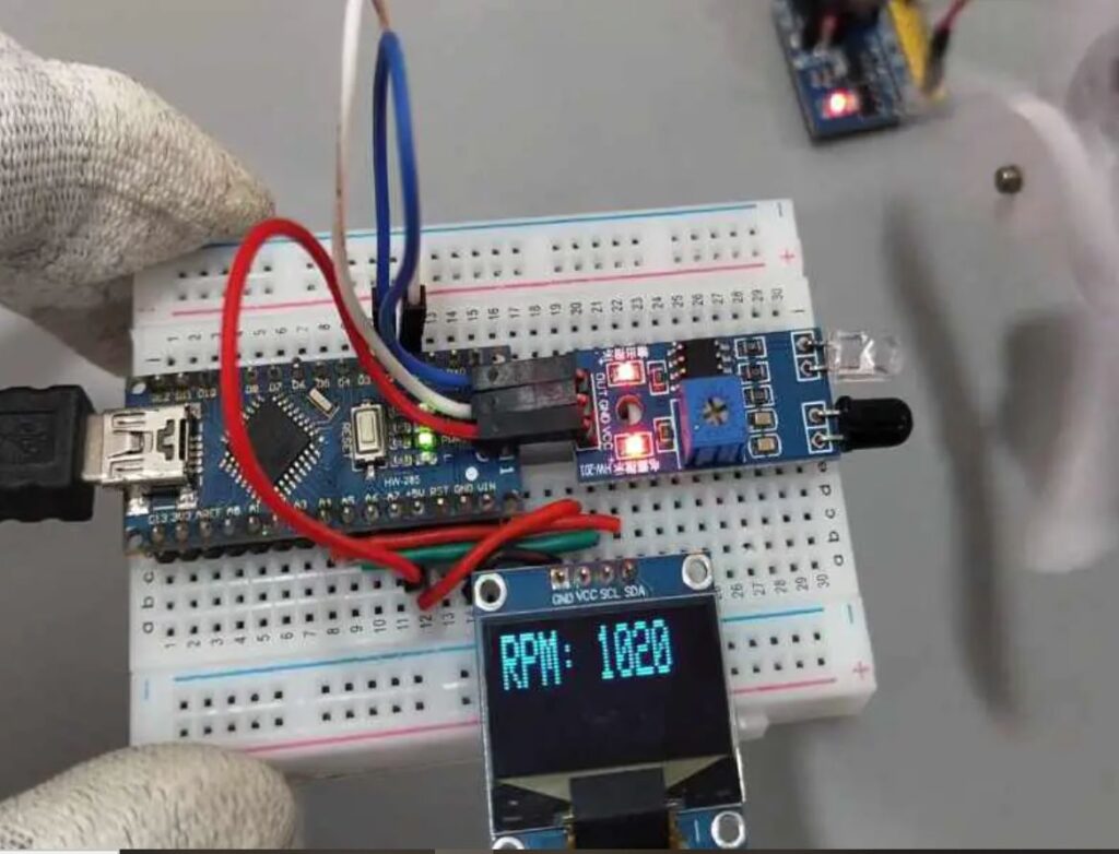
Physical connections
This is a physical connection image of this tachometer.
Arduino Code:
#include <Wire.h>
#include <Adafruit_GFX.h>
#include <Adafruit_SSD1306.h>

#define OLED_RESET 4
Adafruit_SSD1306 display(OLED_RESET);

const int IR_PIN = 5;  // IR sensor input pin

volatile unsigned int counter = 0;  // Counter variable for revolutions
unsigned long previousMillis = 0;  // Variable to store previous time
unsigned int rpm = 0;  // Variable to store RPM value

void IRinterrupt() {
  counter++;
}

void setup() {
  pinMode(IR_PIN, INPUT_PULLUP);
  attachInterrupt(digitalPinToInterrupt(IR_PIN), IRinterrupt, FALLING);

  display.begin(SSD1306_SWITCHCAPVCC, 0x3C);
  display.display();
  delay(2000);
  display.clearDisplay();
  display.setTextSize(2);
  display.setTextColor(SSD1306_WHITE);
  display.setCursor(0, 0);
  display.println("TEG");
  display.display();
  delay(2000);
  display.clearDisplay();
  display.setTextSize(2);
  display.setTextColor(SSD1306_WHITE);
  display.setCursor(0, 0);
  display.println("Tachometer");
  display.display();
  delay(2000);
}

void loop() {
  unsigned long currentMillis = millis();

  if (currentMillis - previousMillis >= 1000) {
    detachInterrupt(digitalPinToInterrupt(IR_PIN));
    rpm = (counter / 2) * 60;  // Calculate RPM
    counter = 0;
    attachInterrupt(digitalPinToInterrupt(IR_PIN), IRinterrupt, FALLING);
    previousMillis = currentMillis;

    display.clearDisplay();
    display.setCursor(0, 0);
    display.print("RPM: ");
    display.println(rpm);
    display.display();
  }
}