To print the values of a 4×4 keypad on a seven-segment display, you will need to interface the keypad and the display with a microcontroller, such as an Arduino. Below is a step-by-step guide to achieve this:
Components Needed:
- 4×4 Matrix Keypad
- Seven Segment Display (Common Anode or Common Cathode)
- Microcontroller (e.g., Arduino Uno)
- Resistors (appropriate values for the seven-segment display)
- Jumper wires
- Breadboard
Step 1: Wiring the 4×4 Keypad
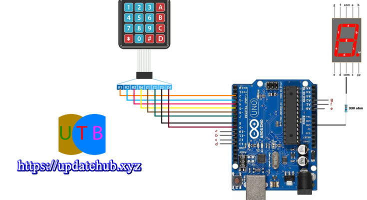
The 4×4 keypad has 8 pins: 4 for the rows and 4 for the columns. Connect these pins to the digital pins of the Arduino.
Step 2: Wiring the Seven Segment Display
The seven-segment display has 8 or 10 pins. If it is a common anode display, connect the common anode pin(s) to a positive voltage. If it is a common cathode display, connect the common cathode pin(s) to the ground. Connect the remaining segment pins (a to g) to the digital pins of the Arduino through current-limiting resistors.
Step 3: Arduino Code
Keypad Library
Use the Keypad library to interface with the keypad. You can install it via the Arduino Library Manager.
Seven Segment Display Control
You can control the seven-segment display using digitalWrite commands or use a library for more complex control. For simplicity, the following code uses direct control.
Step 4: Explanation
- Keypad Wiring: Connect the keypad to the Arduino using the specified row and column pins.
- Seven Segment Display Wiring: Connect each segment pin to the Arduino with current-limiting resistors.
- Code Explanation:
- The
Keypadlibrary is used to handle the keypad inputs. - The segment codes for the numbers 0-9 are defined for a common anode display.
- The
displayDigitfunction controls the segments based on the input digit. - In the
loop, the code continuously checks for key presses and updates the seven-segment display accordingly.
- The
This setup assumes a common anode seven-segment display. If you have a common cathode display, invert the logic in the displayDigit function accordingly.
Circuit Diagram

Code
//YouTube | Ogbugbu Technologies

#include <Keypad.h>
#include <SevSeg.h>

const char number_of_rows = 4;
const char number_of_columns = 4;
char row_pins[number_of_rows] = {2, 3, 4, 5};
char column_pins[number_of_columns] = {6, 7, 8, 9};
int num=0;
SevSeg S;
byte CommonPins[] = {};            // common pin numbers for multi-digit display
byte SegPins[] = {10,11,12,13,A0,A1,A2};  // 7-segment display pins in the order,{a,b,c,d,e,f,g,dp}


char key_array[number_of_rows][number_of_columns] = {
  {'1', '2', '3', 'A'},
  {'4', '5', '6', 'B'},
  {'7', '8', '9', 'C'},
  {'*', '0', '#', 'D'}
  };

Keypad k = Keypad(makeKeymap(key_array),row_pins , column_pins, number_of_rows, number_of_columns);


void setup()
{
  Serial.begin(9600);
    pinMode(10, OUTPUT);
  pinMode(11, OUTPUT);
  pinMode(12, OUTPUT);
  pinMode(13, OUTPUT);
  pinMode(A0, OUTPUT);
  pinMode(A1, OUTPUT);
  pinMode(A2, OUTPUT);
  S.begin(COMMON_CATHODE, 1, CommonPins, SegPins, 1);
}

void loop()
{
 char key_pressed = k.getKey();
num = (key_pressed - '0');   //Conversion from Char to Int
  if(key_pressed)
  {
    Serial.println(key_pressed);
    S.setNumber(num);
    S.refreshDisplay();
    delay(50);
  }

}


